A PAST ARTICLE FROM
REEL DEALS
The Aussie Film Collectors' Magazine
"Keeping Film Collectors in Touch"
The EIKI 16mm
Projector
-
WARNING:
High voltages are present inside the back cover of these projectors.
All work should be performed with the power lead completely unplugged from the power
By no means a service manual or a definitive work on the range of Eiki projectors – this article was written with the hope that some of the information regarding the common problems found when repairing these projectors, may be of assistance to the many owners of these fine machines.
The common models:
ST1 240volt model -
RT0 120volt model -
RT1 240volt model -
NT1 240volt model -
SL1 240volt Slot Loader -
OVERVIEW:
Like most brands of film equipment, genuine spare parts for the Eiki are becoming
increasingly difficult to obtain. There are a number of people offering spares, in
particular belts and lamps. But many parts for these machines are no longer available,
and some ingenuity is required to 'make do'. With the demise of 16mm films as an
educational medium in schools, many of these machines have appeared on the second
hand market at give-
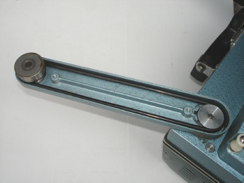
There are 5 belts in the Eiki. The main drive belt from motor to the main shaft, the rewind belt from main shaft to rewind drive clutch, the two reel belts located within the reel arm and the toothed timing belt that drives the sprockets from the main shaft. Fortunately, the toothed belt rarely gives trouble, but the other 4 belts require replacement due to breakage or stretching.
Many of these machines have been sitting around unused for long periods. It is not
uncommon to find that the grease or oil meant to lubricate the shafts, etc may have
become sticky, and is now acting more like glue. All shafts and moving parts should
be checked for free movement. If any of the shafts show a reluctance to move freely,
remove, clean and re-
Fortunately, the design of the EIKI is such that it can be disassembled and reassembled quickly and is relatively easy to repair.
THE COMMON PROBLEMS:
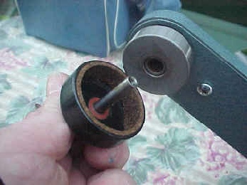
No take-
The take-
Before making the assumption that the cork clutch is faulty, check the rubber belt
within the take-
Note: On some earlier models, there is a screw adjustment to set the take-
No rewind or reverse take-
There are two belts here, one within the arm housing (same as the rear arm -
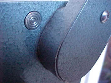
Reel arms wont stay up.
The two round silver release buttons are not popping out when the arms are located in their operate position, due to the grease having become sticky.
Push the locaters buttons forward from inside the machine, and then apply spray lubricant to both front and back of buttons and push in and out until free. If particularly difficult to free up, lay projector on back and ‘flood’ the button with spray lubricant and leave overnight
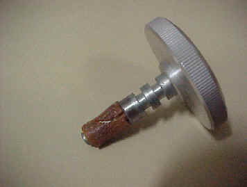
Focus knob inoperative
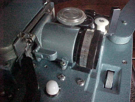
The focus drive shaft has a rubber sleeve which mates with the thread on the lens; this rubber disintegrates or wears away with time. First, remove the lens, and then remove the lens bracket from the machine by loosening the two small locking screws, then loosening the two pivot screws.
Then remove the two small screws and the retaining bracket on top of the lens housing,
now withdraw the focus shaft. The rubber sleeve can be removed from the other end
of the housing. A suitable replacement can be cut from 4mm, thick wall rubber tubing.
To reassemble, refit shaft to housing, apply a small amount of Kwik-
Poor sound quality
This can fall into several categories, which require differing repair techniques. It is essential to make a good diagnosis of the actual problem before ‘diving in’.
Problems can usually be divided into three categories:
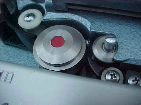
1. Speed variations – or wow. This will be evident on music, particularily slow sustained notes. Check the pressure arm (arrowed), which holds the film against the sound drum shaft – the lubricant on this shaft (and others) often becomes tacky and restricts free movement. Remove the shaft, clean and lubricate. Ensure the flywheel runs freely – it should continue to rotate for quite some time after spinning it.
2. Low level sound -
3. Low level and poor quality sound – If this is an unknown projector, check the exciter lamp – it must be a type BRK 4volt .75amp with a vertical filament. It is not unusual to find the phantom fiddler has fitted a Bell & Howell exciter with a horizontal filament.
Remove the exciter cover and check the exciter lamp voltage (if multimeter available) it should be be a little under 4 volts, a visual check of the exciter should show it to be very bright to look at. If low voltage, it can be the exciter rectifier diodes of the filter capacitor, located in the amplifier chassis.
Amplifier problems
Crackling noises when controls are rotated. This is very common and is generally due to the volume and tone control potentiometers becoming dry over time.
It will be necessary to remove the amplifier chassis – this is surprisingly easy.
First, remove the flywheel by unscrewing its retaining screw – (it may be necessary
to grasp the sound drum from the front of the machine if the screw is tight) Then
unplug the 3.5mm plug to the solar cell and the 9-
Whilst the amplifier is out, a couple of other considerations – spray the lubricant into both the speaker and microphone sockets, now push a suitable plug in and out the sockets several times – this will clean the contacts and ensure a good connection
Line output for external amplifier
It is possible to connect the projector’s speaker output to the input of the amplifier via an attenuator network, but this method means some juggling between the projectors volume setting and that of the external amplifier to get the sound anywhere near reasonable.
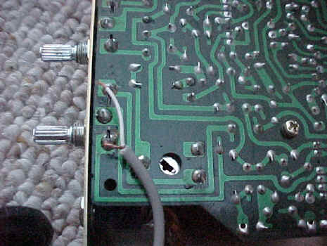
A much better method is to take a line level output from the Eiki. A line level output can be easily fitted by taking the sound off the top volume control potentiometer before the adjustment section. The above picture shows the connections – simply solder a length of shielded cable as shown and either mount a socket on the back cabinet or a fly lead to the amplifier. Better still – if you have no use for the microphone socket – a very simple modification will turn the microphone socket into a line out socket.
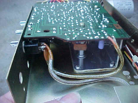
The picture at left shows the shielded cable from the solar cell socket to the switch contacts in the microphone socket and then to the printed circuit board (PCB). Follow the yellow wire coming from the solar cell socket and unsolder it and its shield from the microphone socket – then solder it in place of the other yellow wire and shield where they connect to the PCB.
The wires removed from the PCB are now connected to the volume control – the yellow to the terminal as shown at right.
The microphone socket now becomes a line output socket; its level is independent of the volume setting, so the projector’s volume control will control the internal speaker without affecting the level going to the external amplifier. The projector will operate as normal, with the added bonus of a line output for an external amplifier output.
LENS ALIGNMENT
Under the lens, there is a screw that will adjust the closed position of the lens. Some people believe this is to adjust the film gate tension – wrong!
This screw allows the lens to be adjusted to exactly 90 degrees to the film plane. A degree or so either way and it will be impossible to obtain sharp focus on both left and right sides of the screen simultaneously.
This screw adjustment is quite critical – adjust slowly while viewing the projected picture – at the same time, correct the picture position and focus until the image can be sharply focused from the left edge to right edge of screen simultaneously.
Note: the projector will need tpo be moved to compensate for the horizontal picture
shift that wlll occur as the screw is adjusted -
Sound adjustment
Ideally the exciter lens should be adjusted for best high frequency response – this is best done with a test film and an oscilloscope – However, if necessary, it can be done reasonably well by ear if you dont have the equipment, but if you are unsure, leave it alone – it is unlikely to be out unless the phantom fiddler has been about!
SPARE PARTS
EXCITER LAMPS.
All Eiki machines use a type BRK exciter lamp – this is a 4volt .75watt vertical filament lamp and is readily available.
PROJECTION LAMPS.
Early ST models – 24volt 200watt mirror backed lamp. Type EJL
From RT models onwards – 24volt 250watt type ELC.
LENSES:
Eiki made a wide range of genuine lenses to suit their projectors. The standard lens that came with most machines was a 50mm (2”) lens. Lenses were also available in 38mm (1½”) and 25mm (1”) focal length for a bigger picture, and a 75mm (3”) lens for a smaller picture. Eiki also made a zoom converter lens that screwed onto the front thread of any of their lenses. They also produced an anamorphic lens and bracket that could be fitted for CinemaScope films
LAMPS -
The earlier models used a 200watt 24volt lamp – do not be tempted to fit the more readily available ELC 250watt lamp. This would present a 25% overload on the transformer – half a reel later the transformer will start to smoke.
NOTE RE USE OF "O" RINGS
"O" rings are not intended to be used as belts – they are designed to be used as
a pressure seal between two surfaces -
I have found that some O rings when used as belts will shatter within a few minutes
of starting the machine. For some unexplained reason, I have found that if I buy
a few, 2-

Left:
The rear take-
Right:
The rear clutch unit, note the internal cork ring

Right:
The rewind / reverse run clutch and drive belt assembly
Right:
The latch button which should pop out when the arms are in the up position
Right:
The focus knob with the worn rubber part, removed from its housing
Auto-
Normal operation -
This is generally due to the grease on the auto thread shaft becoming sticky. This
can be a little difficult, but easily fixed. Firstly remove the two screws near the
front of the rear cabinet holding the power transformer in place. Position the transformer
out of the way -

Right:
The slotted screw which retains the auto-
THE AMPLIFIER & SOUND ISSUES
Right: The amplifier chassis removed from the projector.

Exciter lamp -


Final roller and auto-
-
Final drive sprocket
Double roller -
Rotary stabiliser / sound drum -
Exciter lens
Loop restorer arm
Pressure roller
-
Above: The main components in the sound section of the Eiki 16mm projector
Above: Simple cable connection change turns the mic socket into a line output connection
ADDITIONAL NOTES
Copyright Mike Trickett Geelong, Australia 2008 / 2012
Lens alignment screw
